Stress/Strain Transfer in Suspension Bridge Cables
 Focus on Faculty Activities
I. C. Noyan (APAM) Adrian Brügger, Raimondo Betti (Civil Eng./Eng. Mechanics), Bjørn Clausen (LANSCE-LC, Los Alamos National Laboratory)
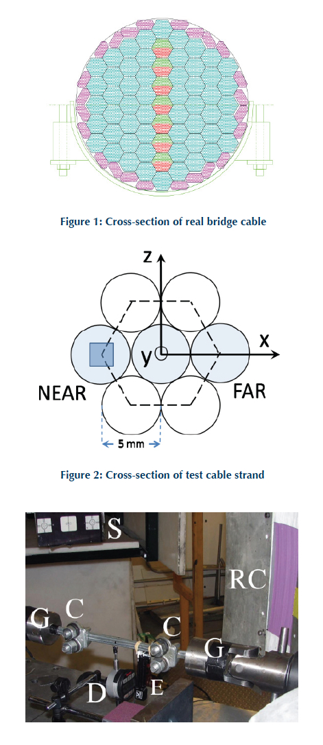
Main cables of suspension bridges are the most critical elements in these structures. Such cables are made of many thousands of parallel high-strength steel wires, whose diameter is about 5 mm. The core of the cable consists of closely-packed galvanized steel wire bundles (strands) (Fig. 1). Each bundle consists of many parallel steel wires whose number depends on the type of cable spinning process used. Inner strands usually have hexagonal cross-sections to optimize the compaction operation. The core is wrapped by a continuous, pre-tensioned wire layer, and it is radially clamped at regular intervals along its entire length to ensure geometrical integrity and tightness, and to enhance strain transfer to any broken wires. Some of the clamping action is also provided by the cable bands that serve as attachment points for the vertical suspenders that connect the bridge deck to the main cable. A mid-sized bridge cable, such as the one used in the Manhattan Bridge in New York, can be about 50 cm (20”) in diameter, with about 8,500 – 9,000 wires while larger cables, approximately 0.9 m – 1 m in diameter (e.g. the Golden Gate Bridge, Verrazano Narrows Bridge and the George Washington Bridge), contain about 26,000 – 28,000 wires. Suspension-bridge cables are loaded in tension: they transfer the entire weight of the bridge deck and any traffic that might be on it, more than several hundred thousand tons, to the suspension towers, and to anchor points at each end of the bridge.
Analysis of load partitioning within such cables is a non-trivial problem and poses theoretical and experimental challenges. The cable can be considered as a massive fiber composite structure that is loaded in the far field. At a location remote from the ends the local stress state within any wire depends on the far-field stress and the local boundary conditions. These local stress/strain states within the cable at the wire level are very hard to calculate since the boundary conditions such as the friction coefficient at the points of contact, local wire flattening, and local contact areas cannot be easily measured or estimated. In addition, because of deterioration or local manufacturing defects, there may be broken wires within the cable, which modify the local stress state in such wires.
We used neutron diffraction at Los Alamos National Laboratory to measure the elastic strains induced in the constituent wires of parallel wire test sample (Figures 2 & 3) under tensile loading; these were the first measurements of their kind. We observed that the elastic strains carried by the individual wires depended very strongly on the boundary conditions at the grips and on radial clamping forces. The friction forces between the wires were quite significant and could not be neglected (which had been the usual procedure).
These results will be published in the Journal of Experimental Mechanics (accepted, in press).
Figure 3: Test Sample mounted in the load tester of the SMARTS Diffractometer at the Los Alamos National Laboratory. The neutron beam from the incident slit (S) impinges on the sample directly above the tip of the dial indicator (D), at the black mark. The extensometer (E) is secured with rubber bands against a bottom wire. The cable clips, C, at each end, exert clamping forces on the entire wire cross-section, including the center wire. The center wire ends approximately 10 mm before entering the conical grips (G). The aperture of one of the radial collimators (RC) is also seen. There are beam-shields on both sides of the RC aperture to minimize stray radiation and background.